CSGShape can be built from any mesh. No further primitives other than those provided by the core jMonkey services are required. However, when working with blending shapes of different textures, I needed finer grained control of how the primitive shapes operated. And I wanted easier XML construction. So the following have been created.
CSGMesh
CSGMesh defines a common design approach to the CSG shape primitives, as well as
providing common services to all the concrete shapes. The primitive is essentially built at
the (0,0,0) origin, with some kind of extent in x, y and z. The shape will have faces
whose texture scaling can be individually controlled and custom Materials applied.
In particular, CSGMesh allows you to:
- Apply different texture scaling to different faces
- Apply different Materials to different faces
- Generate different levels of detail based on LOD Factors
- Produce TangentBinormal lighting information for the Mesh after it is generated
- Common updateGeometry() entry point that rebuilds the shape using all current settings
The java entry points for services above are:
- setFaceProperties( List<CSGFaceProperties> pPropertyList )
- Save the list of face properties pPropertyList and apply them to the appropriate faces when updateGeometry() is triggered. Each CSGFaceProperties instance selects a face (or faces) via a bitmask, and has an optional texture scaling (Vector2f) value and/or custom Material to apply to that face.
- setLODFactors( float[ ] pLODFactors )
- Save the set of percentage load factors that create multiple VertexBuffers when updateGeometry() is triggered. Each specific shape interprets the percentage in its own way, deciding how best to reduce its count of indices by the desired amount. But the end result is to call the underlying Mesh.setLodLevels( VertexBuffer[ ] pLevelsOfDetail ).
- setGenerateTangentBinormal( boolean pFlag )
- Save the flag that, when true, causes TangentBinormalGenerator.generate( thisMesh ) to be called when updateGeometry() is triggered.
- updateGeometry()
- Produce the underlying Mesh (vertices, normal, textures, indices) from the active configuration settings, and then apply texture scaling and tangent binormal generation as needed. No real Mesh is available for this shape until updateGeometry() is called. The final step of Savable.read(...) processing for every CSG shape is to invoke updateGeometry() on itself.
The faces are selected by an integer bitmask where:
0x01 - FRONT
0x02 - BACK
0x04 - LEFT
0x08 - RIGHT
0x10 - TOP
0x20 - BOTTOM
0x40 - SIDES
0x80 - SURFACE
and the logical combination of these values can apply that same properties to multiple faces.
The import XML definitions look something like:
    <mesh class='net.wcomohundro.jme3.csg.shape.CSGSomeShape'
            generateTangentBinormal='true' >
        <faceProperties>
            <net.wcomohundro.jme3.csg.shape.CSGFaceProperties face='FRONT_BACK' scaleX='1' scaleY='1.0'
                materialName='Textures/Rock/Rock1Rpt.xml' />
            <net.wcomohundro.jme3.csg.shape.CSGFaceProperties face='LEFT_RIGHT' scaleX='10' scaleY='1.0'/>
            <net.wcomohundro.jme3.csg.shape.CSGFaceProperties face='TOP_BOTTOM' scaleX='1' scaleY='10.0'/>
        </faceProperties>
        <lodFactors data='0.25 0.50'/>
    </mesh>
CSGBox
CSGBox creates a basic brick shape of given x, y and z extents. The key difference between CSGBox and the standard jme3 Box is its definition of faces (FRONT/BACK/TOP/BOTTOM/LEFT/RIGHT) and the ability to apply different properties to the different sides.
The java entry points for adjusting the configuration include everything from CSGMesh and
- setXExtent( float pExtent )
- setYExtent( float pExtent )
- setZExtent( float pExtent )
- which sets the extent of the box in the given direction. NOTE that the extent applies plus/minus across the origin. So the final width/height/depth is two times the extent value.
The import XML definitions look something like:
    <mesh class='net.wcomohundro.jme3.csg.shape.CSGBox'
            xExtent='5.0' yExtent='1.0' zExtent='1.0' >
        <faceProperties>
            <net.wcomohundro.jme3.csg.shape.CSGFaceProperties face='LEFT_RIGHT' scaleX='5.0' scaleY='1.0'/>
            <net.wcomohundro.jme3.csg.shape.CSGFaceProperties face='TOP_BOTTOM' scaleX='1' scaleY='5.0'/>
        </faceProperties>
    </mesh>
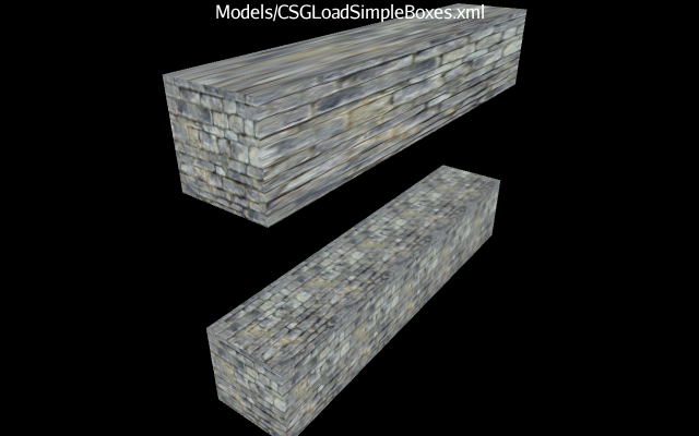
The box on top has had no texture scaling applied, so the texture is stretched to cover the expanded size. The box on the bottom has texture scaling applied to four faces to account for the size.
CSGAxialBox
CSGAxialBox is a minor variant of CSGBox where the texture is applied to the LEFT/RIGHT/TOP/BOTTOM faces just like the texture is applied to the round sides of a cylinder. This helps when aligning textures from blended primitives.
The import XML definition replaces CSGBox with CSGAxialBox
CSGAxial / CSGRadial
CSGAxial is an extension to CSGMesh that defines a common design approach to
those CSG shape primitives that are built of a series of slices along the z-axis. CSGRadial
extends this idea with each slice defined by vertices radially distributed around its center.
CSGRadialCapped is a radial shape with flat end-caps, like a cylinder or a pipe.
The standard faces FRONT/BACK/SIDES apply to all capped radials. A texture mode controls
how the texture is applied to the faces where:
- CAN
- Imagine the shape tilted up to sit on is back face (like a soup can). Then X moves around the circumference, and Y increases upwards on the can.
- ROLLER
- Imagine the shape rotated so that the back is to left and the front is to the right. Then X increases linearly from left to right, and Y increases along the circumference as you move up.
The java entry points configuring the radial are:
- setZExtent( float pZExtent )
- Set the size of the shape along the z-axis
- setAxisSamples( int pSampleCount )
- Set the number of slices to generate along the z-axis
- setRadialSamples( int pSampleCount )
- Set the number of vertices to generate along the outside of each slice. A count of three produces a triangular shape, a count of four produces a square shape, higher counts produce rounder shapes.
- setFirstRadial( float pFirstRadial )
- Set set the angle (in radians) of the first radial from the x-axis. For circular slices, this has minimal effect. But if the count of radial samples is low (3,4,..) then this determines where the first vertex is placed, resulting in a square versus a diamond.
- setRadius( float pRadius )
- The radius to apply to the slice that determines the distance from a vertex to the center.
- setSliceScale( Vector2f pScaling )
- x/y scaling to apply to each individual slice.
(overall scaling of the Geometry that contains this shape does produce an elliptical rather than circular radial. However, the texture applied to each slice is then scaled as well. Applying scale to the individual slice preserves the original texture mapping.) - setSliceRotation( float pTotalRotation )
- The total amount of angular twist (in radians) from the back surface to the front surface, with an appropriate fractional amount applied to each slice.
- setClosed( boolean pIsClosed )
- If true, then the ends of the shape are closed. If false, a hollow shape without ends is constructed.
- setInverted( boolean pIsInverted )
- If true, then the shape is built with its surfaces facing inward. If false, then the surfaces face outward.
The java entry points configuring the capped radial are:
- setRadiusBack( float pRadius )
- The radius to apply to the back face slice that determines the distance from a vertex to the center. When the radius and back radius differ, it will be adjusted on every slice to produce a smooth progression.
- setTextureMode( CSGRadialCapped.TextureMode pTextureMode )
- Set how the texture is applied to the facts.
The import XML definitions look something like:
    <mesh class='net.wcomohundro.jme3.csg.shape.CSGSomeRadial'
            zExtent='3.0' axisSamples='32' radialSamples='32' firstRadial='PI/4'
            radius='1.1' scaleSliceX='2.0' scaleSliceY='2.0' twist='2PI'
            radius2='1.7' textureMode='CAN' >
        ... other definitions from CSGMesh ...
    </mesh>
CSGCylinder
CSGCylinder creates a basic cylinder shape, based on all the setting of CSGRadialCapped. The cylinder can be open or closed, and the two end caps can have a different radius.
The import XML definitions look something like:
    <mesh class='net.wcomohundro.jme3.csg.shape.CSGCylinder'
            zExtent='3.0' radius='1.1' />
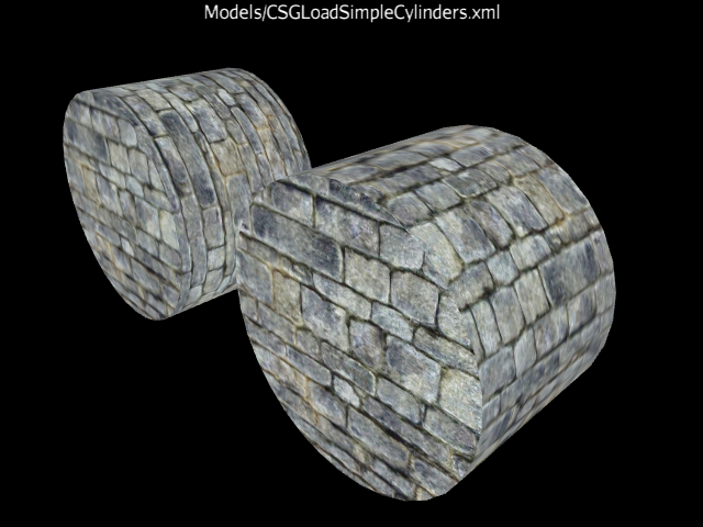
The cylinder on the left applies the texture around the circumference like a CAN. The cylinder on the right applies the texture like a ROLLER. Both have the 'sides' texture scaled to approximate the pattern on the end caps.
CSGSphere
CSGSphere creates a basic sphere shape, based on the setting of
CSGRadial. A sphere has only one face SURFACE (with integral endcaps) and only the single main radius applies.
A sphere marked not closed eliminates the north and south pole slices that converge to a single
point, and tiny holes appear at the extremities instead.
Since sine/cosine vary more rapidly near the right-angle extremes, the sphere can be generated with either
even slices (same distance at each z-axis step) or to generate more slices with a smaller z-axis
step near the right-angle points.
A texture mode controls how the texture is applied to the polar regions (the last section
generated from a common center point to a slice) where:
- ZAXIS
- Wrap texture radially and along the z-axis
- PROJECTED
- Wrap texture radially, but spherically project along the z-axis
- POLAR
- Apply texture to each pole. Eliminates polar distortion, but mirrors the texture across the equator
The java entry points configuring the sphere are:
- setEvenSlices( boolean pFlag )
- If true, generate all equal z-axis steps. If false, generate more slices near the right-angle extremes.
- setTextureMode( CSGSphere.TextureMode pTextureMode )
- Set the texture mode to aplly to the polar caps.
The import XML definitions look something like:
    <mesh class='net.wcomohundro.jme3.csg.shape.CSGSphere'
            zExtent='3.0' radius='1.1' useEvenSlices='false' textureMode='ZAXIS' />
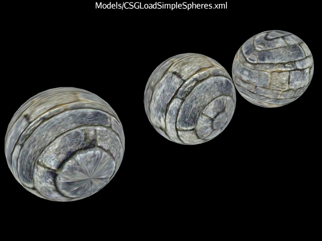
The sphere on the left uses the ZAXIS texture mode. The sphere in the center uses the PROJECTED texture mode. The sphere on the right uses the POLAR texture mode.
CSGPipe
CSGPipe creates a cylindrical shape whose z-axis follows a given spline rather than a straight line. All of the settings of CSGRadialCapped apply. The pipe can be open or closed, and the two end caps can have a different radius. The key parameter is the spline used to generate the z-axis center points for each slice. The slice is expected to be perpendicular to its center point at every interval. Since a single point has no perpendicular, we construct a perpendicular to the line between the current center point and the next. This means the end cap slices can be very sensitive to the structure of the spline. To handle some of the oddities, various PipeEnd custom options are supported where:
- STANDARD
- End slice is generated 'normally', perpendicular to the last point of the curve
- PERPENDICULAR
- End slice is generated perpendicular to the x/y/z axes
- PERPENDICULAR45
- End slice is generated perpendicular/45degree to the x/y/z axes
- CROPPED
- The spline end points do NOT produce a slice, they only influence the last slice normal
Another oddity of building slices along a spline rather than a straight line is that due to the bends in the spline, the slices may collide with each other. This results in a very crumpled looking shape if the spline bends too sharply. An option to 'smooth' the end result is provided. It does the best it can to eliminate the slice overlaps.
The java entry points configuring the pipe are:
- setSlicePath( Spline pCurve )
- Provide a jme3 Spline that determines the position of each slice center point.
- setSmoothSurface( boolean pFlag )
- If true, scan each slice looking for a collision with its neighbor. If an overlap occurs, take action to adjust the slice to eliminate the collision.
- setPipeEnds( CSGPipe.PipeEnds pEnds )
- Control how the ends of the pipe are constructed.
The import XML definitions look something like:
    <mesh class='net.wcomohundro.jme3.csg.shape.CSGPipe'
            pipeEnds='STANDARD' smoothSurface='false >
    	<slicePath class='net.wcomohundro.jme3.csg.shape.CSGSplineGenerator'  arc='PI'/>
    </mesh;>
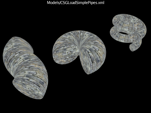
From left to right: spline, torus, helix.
CSGSplineGenerator (helper class)
CSGSplineGenerator is not a shape. Rather, it is a helper class that can assist in the generation of a spline used by CSGPipe. The spline can be defined by:
- An externally defined instance of Spline
- An explicit set of points
- A set of control points interpreted based on the SplineType selected
- A set of generated points around a circular arc, with an optional height adjustment that produces a helix rather than a torus.
The java entry points configuring the pipe are:
- setSpline( Spline pSpline )
- Use the externally produced spline as given.
- setPointList( List
pPointList ) - Use the given set of points rather than a spline.
- setArcRadius( float pRadius )
- Generate an arc of the given radius.
- setArcRadians( float pRadians )
- Generate an arc of the given angle (in radians). A value of 2Pi will generate a complete torus. A value greater than 2Pi is only meaningful for a helix.
- setArcFirstRadial( float pRadial )
- Generate an arc starting with a point at the given angle (in radians).
- setHelixHeight( float pHeight )
- Generate a helix that spans the given height.
The import XML definitions look something like:
    <slicePath class='net.wcomohundro.jme3.csg.shape.CSGSplineGenerator'
    		radius='1.5' arc='PI' firstRadial='PI/4' helix='1.75' />

    <slicePath class='net.wcomohundro.jme3.csg.shape.CSGSplineGenerator'
    		type='Bezier' curveTension='0.5f' cycle='false'>
        <controlPoints>
            <com.jme3.math.Vector3f x='0.0' y='0.0' z='1.5'/>
            <com.jme3.math.Vector3f x='0.45' y='0.0' z='0.75'/>
            <com.jme3.math.Vector3f x='0.45' y='0.0' z='-0.75'/>
            <com.jme3.math.Vector3f x='00' y='0.0' z='-1.5'/>
        </controlPoints>
    </slicePath>
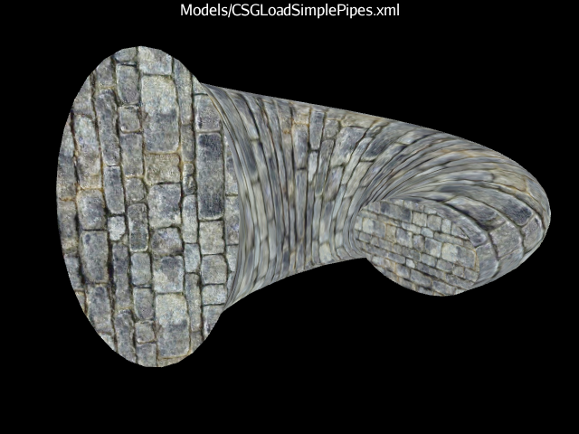
A sample torus, where each slice is scaled in x/y to produce an ellipse, the slices are twisted from front to back, and beginning radius is different from the end radius.
CSGSurface
CSGSurface is not a solid, but rather a 2dimensional surface used as a floor. It is similar to the jme3 Terrain mechanism but lacks the Terrain's LOD support. It operates by producing a Mesh from standard jme3 HeightMap data, with the extents in X/Z, with height in Y.
The java entry points configuring the surface are:
- setExtent( int pSizeOfSquareArea )
- The width and depth of the area (a value of 2**N + 1 is required)
- setHeightMap( float[] pHeightMap )
- The height of each data point.
- setScale( Vector3f pScale )
- The scale to apply to all the data points.
The import XML definitions look something like:
    <mesh class='net.wcomohundro.jme3.csg.shape.CSGSurface' extent='129'>
        <faceProperties>
            <net.wcomohundro.jme3.csg.shape.CSGFaceProperties
					face='SURFACE' scaleX='1032' scaleY='1032'/>
        </faceProperties>
        <heightMap class='net.wcomohundro.jme3.csg.shape.CSGHeightMapGenerator'
            			type='HILL' size='129' scale='0.025' seed='12345' />
    </mesh>
CSGHeightMapGenerator (helper class)
CSGHeightMapGenerator is not a shape. Rather, it is a helper class that can assist in building the HeightMap data used by CSGSurface. It includes support for the basic jme3 classes within com.jme3.terrain.heightmap. In particular, the types are:
- DISPLACEMENT
- uses MidpointDisplacementHeightMap
- FAULT
- uses FaultHeightMap
- FLUID
- uses FluidSimHeightMap
- HILL
- uses HillHeightMap
- PARTICLE
- uses ParticleDepositionHeightMap
The import XML definitions look something like:
    <heightMap class='net.wcomohundro.jme3.csg.shape.CSGSplineGenerator'
    		type='HILL' size='257' iterations='100' seed='0'
    	... type specific parameters here, @see the code itself ...
    />
CSGFaceProperties (helper class)
CSGFaceProperties is not a shape. Rather, it is a helper class that can assist in applying custom materials and texture scaling to different faces in a CSGMesh. In most regards, a CSGMesh plays the part of a standard jme3 Mesh. And while a Mesh understands its own Texture Coordinate mapping, it has no knowledge of the Material that is applied. Material is defined and applied by the Geometry that contains the Mesh.
But within the CSG realm, it becomes very handy if the underlying CSGMesh can associate a different Material to different faces. For example, say you are going to define a Room by subtracting a smaller inner Box from a slightly larger outer Box. If you want different materials applied to the floor versus the ceiling versus the walls, then you are stuck using some kind of Material mapping convention or by using multiple primitives to represent the various components.
Since CSGMesh understands custom Materials mapped to its various faces, and since CSGGeonode understands operating with multiple Materials, in becomes quite easy to define face-specific Materials directly on CSGBox, and let the CSG standard processing apply the proper Material to the appropriate surfaces.
Note that to the core jme3 processing, a CSGBox is just a Mesh. There is no core process to notice that custom Materials have been defined at the Mesh level. But the CSGShape processing does understand multiple Materials applied to primitives, and it especially looks for CSGMesh. So if you include a CSGBox with custom Materials with a jme3 Geometry node, those Materials are ignored. But if you include that same CSGBox via a CSGShape added to a CSGGeonode, then the custom Materials are used.
CSGFaceProperties is also used to control the texture scaling and positioning that applies to a face. This addresses the issue of a box elongated in z, but not in x and y. In that case, the front and back faces should retain unit texture scaling. But the left/right/top/bottom faces should be scaled appropriately to prevent the texture from stretching.
In addition to scaling the texture, you can also control its origin and span. Typically a texture runs from 0.0 to 1.0 across a face. Scaling can account for a face that is a different size. But when blending primitives together, you may want the texture of a subcomponent to align with the texture of the larger component. Think of building dice, with pips. You could create such an item by subtracting a smaller cylinder multiple times from a larger cube. But if you want the texture pattern to be continuous across the pips, then you have to set an appropriate texture origin to each cylinder.
As well as texture, you can control physics properties per face. In the example of building a Room, you might want bouncy walls but an inert floor. This can be done by defining different Physics properties to the different faces.
In any case, CSGFaceProperties applies to a face or faces, as determined by a bitmask of all the faces involved.
The import XML definitions look something like:
    <faceProperties>
	    <net.wcomohundro.jme3.csg.shape.CSGFaceProperties face='FRONT_BACK' scaleX='1' scaleY='1.5'
		        materialName='Textures/Rock/Rock1Rpt.xml'/>
        <net.wcomohundro.jme3.csg.shape.CSGFaceProperties face='LEFT_RIGHT' scaleX='2' scaleY='1.5'
		        materialName='Textures/BrickWall/BrickWallRpt.xml'/>
        <net.wcomohundro.jme3.csg.shape.CSGFaceProperties face='TOP_BOTTOM' scaleX='1' scaleY='2.0'/>
    </faceProperties>